

Structural Dynamics Test of Spiral Tube Actuator for Controlled Extension / Retraction (STACER) Antenna Deployment in Microgravity
PI: Kerri Cahoy, Massachusetts Institute of Technology
PI: Kerri Cahoy, Massachusetts Institute of Technology
- TA08 Science Instruments, Observations and Sensor Systems
- TA12 Materials, Structures, Mechanical Systems and Manufacturing
The STACER antenna poses two challenges to the TERSat mission: (1) The deployment mechanism has several possible modes of failure, some of which can be influenced by gravity, (2) It is important to understand the structural resonant frequency and behavior of the STACER for designing the satellite control algorithms, but STACER dynamics are difficult to measure on the ground.
The STACER deployment system is currently at TRL 4. To fulfill TRL 6, the STACER system must undergo operational testing in microgravity, such as on parabolic flight.
MIT, AFRL, NASA
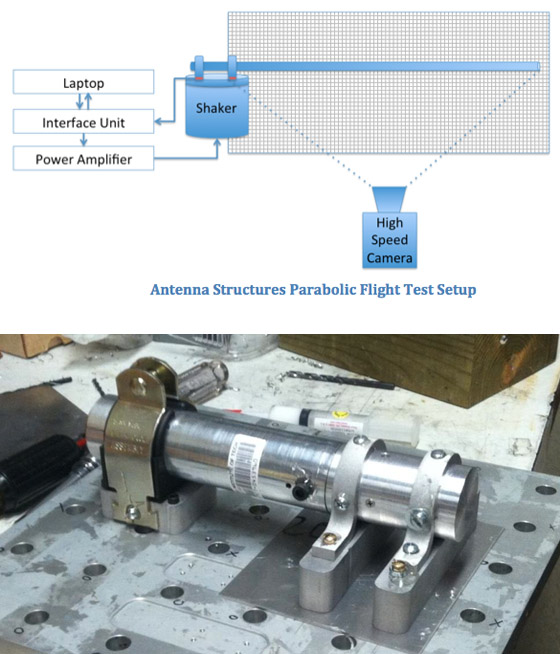
Each microgravity flight will consist of deployment testing followed by operational testing of the STACER system. This test involves applying a voltage to a Frangibolt (a low-risk voltage-driven actuator) that fastens the top of the STACER to the base of its casing. When the Frangibolt activates, a bold holding the tip piece will sever, causing the STACER to deploy outward due only to its stored spring energy. Since it is logistically impractical to re-stow the STACER for a second deployment in the same flight, the dynamics of the STACER will be tested over the rest of the parabolas of a single flight. A miniature shake table system controlled by a laptop will produce a sine sweep excitation through 100 Hz to 200 Hz per parabola, allowing engineers on-board to study the effects of the excitation. A high-speed camera will capture the motion for post-processing of data.
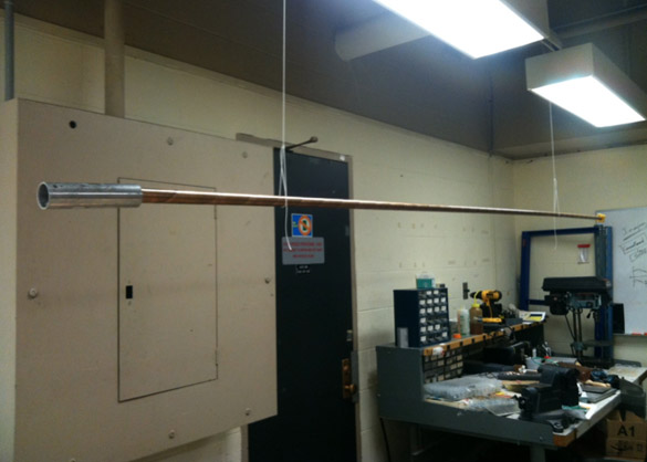
The payload is composed of a STACER housed in a custom-made aluminum case. The STACER Deployment System is 2.73 m long. Supporting test equipment will take an additional 0.5 m.
Technology Details
-
Selection DateAFO5 (Jan 2013)
-
Program StatusCompleted
- 1 Parabolic
Development Team
-
PIKerri Cahoy
-
Organization
-
SponsorAFRL University Nanosatellite program